Ray originating from a virtual surface element
Generation and Processing of Ray Data from an LED Measured with the RiGO801-LED Goniophotometer
Application Note – AN2003
This page summarizes the contents of the Application Note, which provides a practical guide to processing a TechnoTeam TTR rayfile based on an LED measurement. Using the TechnoTeam software Converter801, it demonstrates how to prepare the file for general applications and generate ray data in various file formats.
TechnoTeam Ray data in TTR File Format
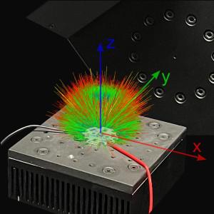
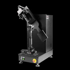
TechnoTeam RiGO801 goniophotometers use the near-field measurement principle with an LMK imaging luminance measurement camera (ILMD [1]) to capture ray data, which is stored in the proprietary TTR format. Using the free Converter801 software, these data can be converted into common formats such as IES TM-25 [2], LightTools, Zemax, and TracePro.

Ray data
A ray represents the luminous flux or radiant flux emitted from a (virtual) surface element of a light source in a specific direction. Additionally, the ray can be assigned further characteristics, such as spectral data. A sufficiently high number of such rays enables an accurate representation of the emission characteristics of a light source. The resulting dataset is referred to as ray set, commonly known as a rayfile.
Generation of Rays from the TTR File Format
A TTR file stores rays as image sequences with associated camera positions. Through coordinate transformations, vectors are generated from the image data within the goniometer coordinate system. The ray starting points are shifted onto an enclosing surface (target geometry) around the light source. Two modes are available:
- Surface Mode: Rays are positioned on the surface of the target geometry.
- Volume Mode: Rays are placed inside the target geometry.
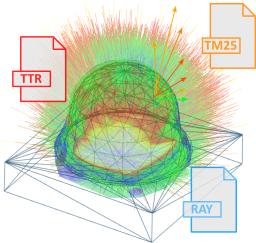
Exporting Ray Data into Various File Formats
The computed rays can be exported into formats compatible with optical simulation software such as LightTools, Zemax, TracePro, and ASAP. Standards like IES TM-25 ensure compatibility and efficient data processing.
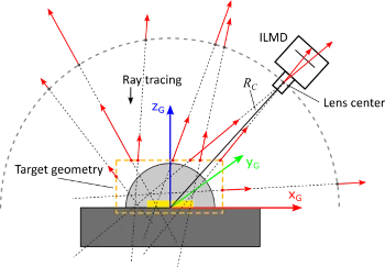
Shifting of starting points onto a target geometry
Generation of Rayfiles for the Measured LED
This section explains the creation of a rayfile based on TTR measurement data of a white LED (ams OSRAM LCW CP7P, see Application Note AN2002). The process includes defining the target geometry and coordinate systems, as well as verifying the generated rays.
Opening the TTR File
The TTR file is loaded via "File → Open …", displaying an overview with all contained data in tabbed sections. A detailed description can be found in related documents such as the Measurement Manual and the Converter801 Software Manual.
Defining and Verifying the Target Geometry
To accurately set the target geometry, it is essential to know the LED’s position within the goniometer coordinate system. This information can be extracted from LED alignment images stored in the additional data section of the TTR file.

Position of the cylindrical target geometry relative to the LED
At first glance, a cylinder or a sphere appears to be a suitable choice for the target geometry. For initial testing, a cylinder is defined to enclose the LED lens. With an additional 0.1 mm margin, the cylinder has a diameter of 2.2 mm and a height of 1.8 mm, with its center positioned at 0.8 mm. These settings can be configured under "Options → Target Geometry…".
To verify the suitability of the selected target geometry parameters, a test dataset with 1 million rays is generated, for example, in the LightTools format (Convert → LightTools Rayfile (*.ray)). Rays that do not intersect with the target geometry are omitted from the final file. The number of exported rays serves as a validation criterion for the target geometry parameters. In this case, only 979,028 rays were successfully exported, resulting in a loss of 2.1%. If the deviation exceeds 1%, a detailed analysis of the missing rays is recommended, and adjustments to the target geometry may be necessary.
By enabling the “Save excluded rays” option, non-exported rays are stored in a separate file with the suffix "_excluded" To ensure a sufficiently large dataset for analysis, a file containing 100 million rays is generated.
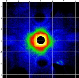
Origin of excluded rays on the X/Y plane
The result of ray tracing these rays onto the X/Y plane is shown alongside. As expected, a significant portion of the LED emission is reflected by both the LED housing and the PCB, particularly in the near-field region. If this approximately 2% portion of the rays is to be considered, the target geometry must be expanded. A cuboid target geometry with dimensions 3.2 mm × 3.2 mm × 1.8 mm is a suitable option. A subsequent test conversion with these parameters results in only 1% of rays being excluded, making them the preferred settings.
Defining Surface or Volume Mode
The default mode for determining the ray starting points is the surface mode, where intersections with the target geometry's surface are calculated. In volume mode, the starting points are placed at the midpoint between the two intersection points. This mode is particularly useful here since choosing a cuboid geometry and adapting it to the LED housing dimensions leads to larger distances between the ray starting points and the actual light-emitting areas.

Ray starting points on the surface (left) and in the volume (right)
Processing the TTR File for General Use
The finalized settings are embedded into the TTR file via “File → Edit …”, which opens an extended editing window. Here, various adjustments can be made, and unnecessary information can be removed.
Details of Measurement
In the “Details of Measurement” tab, general data such as measured luminous flux and camera settings can be modified. Internal data that are not relevant for external users (e.g., file paths) can be selected and deleted using checkboxes. Essential parameters for ray data export, including target geometry and coordinate system, are finalized and applied in this section.

Processed additional data of the TTR file
Adding Spectral Data
A spectral distribution can be assigned to the TTR file, for example, from a goniospectrometric measurement in the TechnoTeam TSD format. These data enable the generation of spectral rayfiles or serve as additional reference information.
Additional Data
The TTR file allows the inclusion of structured supplementary data, such as alignment images or documentation. In this example, the list of alignment images is filtered, keeping only the two essential images, which are then renamed. Additionally, two subfolders are created to store the full goniospectrometric measurement data and the LED datasheet.
Generating Rayfiles with the Processed TTR File
Once the TTR file is fully processed, rayfiles can be generated based on the adjusted target geometry, coordinate system, and spectral data.
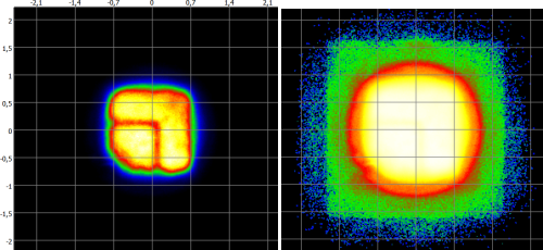
Raytracing on the X/Y plane (linear and logarithmic scaling)
Single Processing
After loading the TTR file, the desired export format can be selected via the conversion dialog. It is essential to activate the option "Use target geometry and coordinate system from the TTR source file" to apply the embedded parameters. To illustrate the results, a rayfile with 100 million rays is generated and mapped onto the X/Y plane.
Batch Processing
For generating multiple file formats or varying numbers of rays, the "Convert → Batch Processing" function is recommended. This feature allows for automated conversions by defining parameters and output formats in advance, saving time and reducing manual effort. A detailed guide on batch processing can be found in the Converter801 software manual.
Summary
This Application Note demonstrates how to generate ray data from a measured TTR file and export it to various formats. The focus was on defining the target geometry and analyzing reflections outside the light emission volume. The processed TTR file is optimized for general use without requiring in-depth knowledge of the measurement process.
Further topics, such as the generation of spectral ray data, particularly for white phosphor-converted LEDs, are covered in separate Application Notes.
Download
References
| [1] | CIE 244:2021: "Characterization of Imaging Luminance Measurement Devices (ILMDs),“ CIE, 2021. |
| [2] | IES TM-25: "Ray File Format for Description of the Emission Properties of Light Sources", Illuminating Engineering Society, 2020 |